留言
如果您对我们的产品感兴趣并想了解更多详情,请在此留言,我们会尽快回复您。

The fire truck PTO (Power Take-Off) is a power transmission device that transfers engine power to the fire pump. When the firefighter activates the PTO, mechanical power from the engine is transmitted through the transmission and PTO to the fire pump — this is the core working principle of how a fire fighting truck PTO system operates — enabling the pump to deliver high-pressure, high-flow water or foam without the need for a separate auxiliary engine.
Modern fire trucks typically use side-mounted PTO or full power PTO systems. These offer stable power output, convenient operation, and low maintenance costs, making them an essential component of the fire truck's firefighting system.
 Work")
PTO (Power Take-Off) is a critical component in the fire truck's power system. It is a gear transmission device installed between the engine and the transmission, designed to "divert" a portion of mechanical power from the vehicle's engine or transmission to the fire pump or other auxiliary equipment, without affecting the vehicle's normal driving capability.
The fire truck engine is originally responsible only for driving the wheels. However, once the fire truck arrives at the fire scene, the wheels no longer need power, while the fire pump requires power to draw and pressurize water. The PTO is the device that accomplishes this "power switch."

Power Take-Off (PTO) literally means "power output device."
On a fire truck, it refers to extracting rotational power from the engine flywheel or transmission gears through gear engagement, and delivering it to the fire pump or other auxiliary equipment.
Its name describes its function:
Engine = Power source
PTO = Power distributor
Fire pump = Power consumption end
Therefore, the PTO is the bridge connecting the "power source" and the "firefighting system."
The core reason fire trucks must be equipped with a PTO is that firefighting operations require continuous, stable, high-power output that cannot rely on the vehicle's driving state.
Main reasons:
1. Provides continuous firefighting power
The fire pump needs to run for extended periods during firefighting operations. The PTO allows the engine to continuously drive the fire pump at idle or fixed RPM, ensuring stable water pressure and flow.
2. Improves power utilization efficiency
Without a PTO, a separate auxiliary engine would be required to drive the fire pump, which would increase:
Cost
Maintenance complexity
Risk of failure
Space occupation
The PTO directly utilizes the vehicle's engine power, improving overall efficiency.
3. Supports multiple firefighting systems
Modern industrial fire trucks may include not only water pumps but also:
Foam systems
Dry powder systems
High-pressure water systems
Remote-controlled fire monitors
Without a PTO, there are only two solutions:
Install a separate engine to drive the pump → increases weight, cost, maintenance points, and occupies space
Keep the pump permanently connected to the transmission → pump stops when vehicle stops, unable to pump water on site
The PTO solves both problems at once:
| Mode | PTO Status | Power Destination | Result |
| Driving mode | Disengaged | All to wheels | Normal driving |
| Firefighting mode | Engaged | All to fire pump | Pumping while stationary |
The PTO is essentially a "power distribution and conversion system" that transforms vehicle driving power into firefighting operational power.
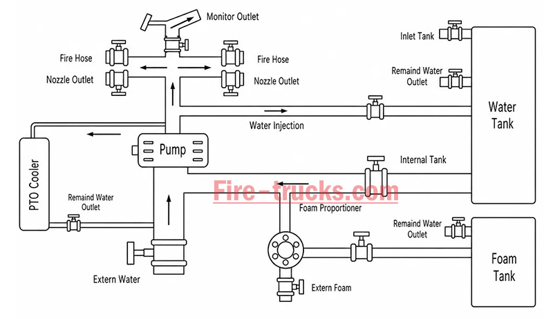
From an engineering perspective, the complete power path is:
Engine → Transmission → PTO → Drive Shaft → Fire Pump → Fire Monitor/Hose System
The PTO's working principle can be summarized in three key stages: power take-off, engagement, and transmission.
The PTO draws power from the engine. Depending on the installation position, the power take-off method differs:
| PTO Type | Installation Position | Power Source | Characteristics |
| Side-mounted PTO | Transmission side | Transmission countershaft gear | Simple structure, lower power (≤50% engine power) |
| Sandwich PTO | Between engine and transmission | Engine flywheel | Full power output, mainstream configuration |
| Split-shaft PTO | Between transmission and driveshaft | Transmission output shaft | High power, allows pumping while driving |
After the driver presses the PTO switch in the cab, the engagement mechanism activates:
| Engagement Method | Working Principle | Common On |
| Electric solenoid control | Electrical signal activates solenoid, pushing shift fork | Mainstream on modern fire trucks |
| Pneumatic control | Compressed air pushes piston, actuating fork | Large fire trucks |
| Manual cable | Mechanical cable directly pulls fork | Older vehicles |
Operation sequence:
Press PTO switch → Solenoid/cylinder actuates → Shift fork pushes sliding gear → Meshes with flywheel or transmission gear → Power connected
After the PTO output shaft begins rotating, power is transmitted through the drive shaft to the fire pump:
PTO output shaft rotates → Drive shaft → Fire pump input shaft → Pump impeller rotates → Water is pressurized and discharged
| Step | Action | Result |
|---|---|---|
| Step 1 | Engine starts, vehicle idling or driving | Engine running, PTO disengaged |
| Step 2 | Arrive at scene, driver presses PTO switch | Driving power disengaged (on some models), PTO gear activated |
| Step 3 | PTO establishes power connection with transmission | Transmission power is diverted to PTO output shaft |
| Step 4 | Drive shaft transmits power to fire pump | Fire pump begins receiving continuous mechanical power |
| Step 5 | Fire pump impeller rotates at high speed | Suction → Pressurization → Delivery to discharge lines → Firefighting |
| Step 6 | System reaches balanced RPM | Stable output, adjustable pressure, flow, and spray pattern |
The fire truck PTO system is a complete power transmission chain, with multiple components working together to transfer engine power to the fire pump. The system can be broken down into six core components:
The engine is the power source of the PTO system and the heart of the entire fire truck.
Function: Generates raw rotational power, driving the flywheel or crankshaft.
Power output: Typically 300–600 HP (depending on chassis model and configuration).
Relationship with PTO: The PTO draws power from the engine flywheel or crankshaft — it is the starting point of power.
Key characteristic: Engine RPM directly affects PTO output speed and the fire pump's water discharge capability. Fire trucks are typically equipped with high-power diesel engines, which not only drive the vehicle but also provide ample power reserve for the fire pump. After PTO engagement, the operator can control pump discharge pressure by adjusting engine RPM.
The transmission is responsible for power delivery and speed matching.
Function: Receives engine power and adjusts speed and torque through different gear combinations.
Relationship with PTO: Side-mounted PTO draws power from internal transmission gears; sandwich PTO is installed at the front of the transmission.
Key characteristic: Transmission gear position does not affect PTO output speed — PTO operates independently of gear selection.
Two power take-off positions:
Transmission side window take-off: PTO mounted on transmission side, drawing power from countershaft or intermediate shaft gears; common on medium-duty fire trucks.
Transmission rear-end take-off (sandwich): PTO installed between engine and transmission, drawing power directly from the flywheel, enabling full power output.
The PTO is the core of the entire system, responsible for "extracting" power from the engine and delivering it to the fire pump.
Function: Extracts power from the engine or transmission and converts it to the speed and torque suitable for the fire pump.
Installation position: Transmission side (side-mounted) or between engine and transmission (sandwich).
Key characteristic: Determines power transmission efficiency, speed matching, and operational convenience.
The drive shaft is the "power bridge" connecting the PTO and the fire pump.
Function: Transmits rotational power from the PTO output shaft to the fire pump input.
Structure: Typically consists of a metal shaft tube, universal joints, and splined connections.
Key characteristic: Must be precisely aligned to avoid vibration; universal joints allow angular compensation.
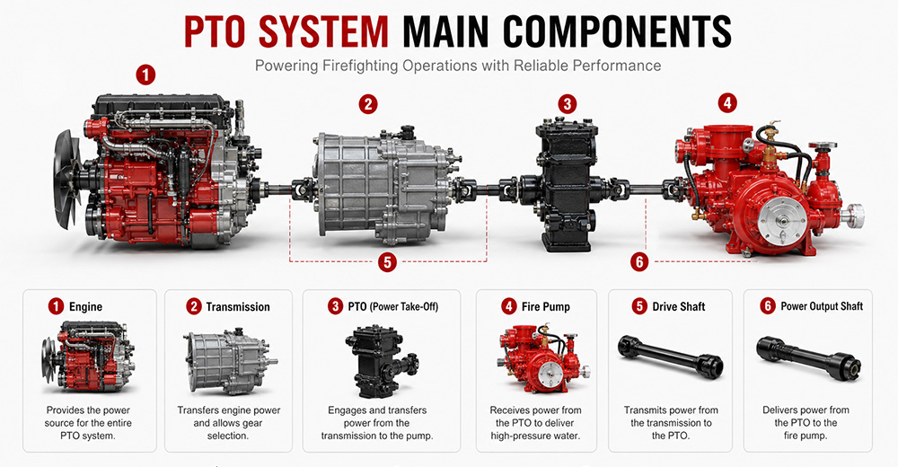
The fire pump is the final load of the PTO system, responsible for converting mechanical energy into water pressure energy.
Function: Receives rotational power from the PTO, drives the impeller to rotate, draws water in, and discharges it under high pressure.
Type: Centrifugal pump (single-stage, two-stage, or multi-stage).
Typical flow rate: 20 L/s – 180 L/s (1,200 – 6,000 L/min).
Typical pressure: 1.0 – 2.5 MPa (10 – 25 bar).
The PTO control system is the "command center" between the driver and the PTO system, responsible for engagement, disengagement, safety protection, and status indication.
Function: Controls PTO engagement and disengagement, monitors system status, and provides safety protection.
Operating location: Cab interior (primary control) and pump panel (auxiliary control).
Control methods: Manual cable, electric solenoid, pneumatic.
Specific control functions:
(1) PTO Engagement Control
The operator presses the PTO switch (electric solenoid/pneumatic) or pulls the lever (manual) in the cab. The control system sends a signal to engage the PTO's internal gears with the power source. After successful engagement is confirmed, an indicator light illuminates, allowing the operator to increase engine RPM.
(2) PTO Disengagement Control
The operator presses the switch again or resets the lever. The control system cuts the signal, and the PTO gears disengage. After disengagement is confirmed, the indicator light turns off.
| PTO Type | Installation Position | Power Source | Power Output | Typical Application |
| Sandwich PTO | Between engine and transmission | Engine flywheel | Full power (≥90%) | Fire pumpers, aerial trucks |
| Split-shaft PTO | Middle of chassis driveshaft | Transmission output shaft | Full power | Large vacuum trucks, airport fire trucks |
| Side-mounted PTO | Transmission side | Transmission gears | Partial power (lower) | Sprinkler trucks, small vacuum trucks |
Sandwich PTO
Advantages: Full power output (≥90%), supports "pumping while driving" (dual-function), high transmission efficiency, easy lubrication.
Disadvantages: Higher cost, complex installation, requires modification to the engine-transmission connection.
Split-shaft PTO
Advantages: Full power output, no additional space required, high reliability, good dynamic balance, can replace auxiliary engine to drive large pumps.
Disadvantages: Requires cutting the original driveshaft, installation position selection must consider driveshaft angle and length compensation.
Side-mounted PTO
Advantages: Low cost, simple installation, can draw power directly from the transmission side.
Disadvantages: Only partial power available, lower output torque, cannot drive high-power fire pumps, mainly used for low-speed, low-power equipment.
 for Fire Trucks")
The process follows a clear mechanical transmission chain:
Engine → PTO → Drive Shaft → Fire Pump → Impeller Rotation → Suction → Pressurization → Fire Monitor
| Factor | Role |
|---|---|
| Centrifugal pump characteristic | When impeller speed is constant, discharge pressure remains naturally stable |
| PTO rigid connection | No slippage or power loss, ensuring continuous stable power input |
| Pressure governor | Automatically detects flow changes and adjusts engine RPM to maintain set pressure |
| Relief valve | Automatically bypasses when pressure exceeds limit, preventing equipment damage |
① Pump speed is determined by engine RPM
Fire pump impeller speed = Engine RPM × PTO ratio. The PTO ratio is fixed (e.g., 1.75:1), so pump speed changes directly with engine RPM.
Calculation formula:
Engine RPM × PTO ratio = Pump speed (RPM)
② Physical relationship between pressure and speed
The pressure generated by a centrifugal pump is proportional to the square of the impeller speed. This physical law means that small changes in RPM cause significant pressure fluctuations.
Speed increases → Centrifugal force increases → Discharge pressure rises
Speed decreases → Centrifugal force decreases → Discharge pressure drops

1. PTO will not engage
Possible causes: Low air pressure (pneumatic type), faulty solenoid, damaged or stuck cable, interlock conditions not met (parking brake not applied, transmission not in neutral).
Solutions: Check air system pressure (must be ≥0.6 MPa); test solenoid; inspect cable; confirm parking brake is applied and transmission is in neutral.
2. PTO engages but pump does not work
Possible causes: PTO clutch failure, broken drive shaft or worn splines, damaged internal gears.
Solutions: Check PTO clutch engagement; inspect drive shaft for breakage or loose connections; disassemble and inspect internal gears.
3. PTO unusual noise
Possible causes: Poor gear meshing or wear, worn bearings, insufficient or degraded lubrication, PTO not fully disengaged.
Solutions: Check gear clearance and tooth wear; inspect bearings; replace with qualified lubricant; confirm PTO is fully disengaged.
4. PTO oil leakage
Possible causes: Worn or deteriorated seals, cracked housing, loose mounting bolts.
Solutions: Replace seals (O-rings, oil seals); inspect housing for cracks; tighten mounting bolts.
5. PTO overheating
Possible causes: Prolonged high-load operation, insufficient or degraded lubricating oil, cooling system failure.
Solutions: Reduce load or shut down for cooling; replace with qualified lubricant; inspect cooling lines.
6. PTO insufficient power
Possible causes: Improper PTO ratio selection, engine RPM set too low, clutch slippage.
Solutions: Confirm PTO ratio matches the fire pump; increase engine RPM to rated operating range; inspect clutch for slippage.
Q1. What does PTO stand for on a fire truck?
PTO stands for Power Take-Off. It is a mechanical system that transfers engine power from the truck's transmission to the fire pump. In simple terms, PTO allows the fire truck's engine to power the pumping system so it can deliver high-pressure water or foam for firefighting operations without needing a separate engine. It is a critical component in industrial and municipal fire trucks.
Q2. Why do fire trucks need a PTO?
Fire trucks need a PTO because it enables the vehicle's main engine to drive the fire pump efficiently. Without a PTO, the fire pump would require a separate engine, which increases cost, weight, and maintenance complexity. PTO systems provide a compact, reliable, and fuel-efficient way to ensure continuous water or foam supply during firefighting operations.
Q3. Can a fire truck operate without a PTO?
Most modern fire trucks cannot operate their pumping system without a PTO because the PTO is responsible for transferring engine power to the fire pump. However, some specialized fire vehicles may use an independent auxiliary engine to drive the pump. These designs are less common due to higher cost, increased maintenance, and lower efficiency compared to PTO-based systems.
Q4. What is the difference between PTO and a fire pump?
The PTO is a power transmission device, while the fire pump is a water or foam pumping system. The PTO delivers mechanical power from the engine to the pump, and the fire pump converts that power into hydraulic pressure to move water or foam. In short, PTO is the "power source connector," and the fire pump is the "firefighting output device."
Q5. How much power can a fire truck PTO provide?
The power output of a fire truck PTO depends on the vehicle design and transmission system. Typically, PTO systems can provide between 50 kW to over 300 kW of mechanical power. Heavy-duty industrial and airport fire trucks often use high-capacity PTO systems capable of supporting large-flow fire pumps and continuous high-pressure operations.
Q6. What are the different types of fire truck PTOs?
There are several types of fire truck PTO systems, including side-mounted PTO, rear-mounted PTO, split shaft PTO, and full power PTO. Side-mounted PTO is commonly used in standard fire trucks, while split shaft and full power PTO systems are used in industrial and airport fire trucks where higher power output and continuous operation are required.
Q7. How do you maintain a fire truck PTO?
PTO maintenance includes regular inspection of lubrication oil levels, checking for leaks, tightening mounting bolts, and ensuring proper alignment of the drive shaft. Operators should also test engagement and disengagement functions regularly. Preventive maintenance is essential to avoid overheating, mechanical wear, and unexpected failure during emergency operations.
Q8. What causes a fire truck PTO to fail?
Common causes of PTO failure include insufficient lubrication, worn gears, misalignment of the drive shaft, overheating, and improper operation by the driver. Electrical or hydraulic control system failures can also prevent PTO engagement. Regular maintenance and correct operating procedures significantly reduce the risk of PTO failure.
Q9. Which PTO is best for industrial fire trucks?
For industrial fire trucks, the best option is usually a split shaft PTO or full power PTO system. These systems can handle high power output, continuous operation, and large-capacity fire pumps. They are widely used in petrochemical plants, refineries, airports, and large industrial facilities where reliable and long-duration firefighting performance is required.
Q10. What should buyers consider when choosing a fire truck PTO?
Buyers should consider engine power compatibility, required fire pump flow rate, vehicle type, and working environment. It is also important to evaluate PTO durability, cooling performance, maintenance accessibility, and compatibility with the chassis. For export projects, compliance with international standards and local regulations should also be taken into account to ensure approval and operational reliability.
PTO (Power Take-Off) is the core system that transfers engine power to the fire pump — it determines whether the entire firefighting system can operate properly.
The fire truck power chain is: Engine → Transmission → PTO → Drive Shaft → Fire Pump → Fire Monitor. Any weak link in this chain affects final firefighting performance.
The primary function of the PTO is to provide stable, continuous mechanical power output, enabling the fire truck to deliver efficient water or foam supply without requiring a separate engine.
Different PTO types (Side-mounted, Rear-mounted, Split shaft, Full power) are suited to different fire truck classes. Industrial fire trucks typically prioritize high-power PTO systems.
PTO performance must match the fire pump flow rate and vehicle chassis, otherwise issues such as insufficient power, unstable pressure, or system overload may occur.
Regular PTO system maintenance (lubrication, tightening, alignment inspection) is key to ensuring reliable fire truck operation, especially in high-intensity industrial applications.
When purchasing industrial fire trucks, buyers should not focus solely on price. PTO power, stability, compatibility, and after-sales support are equally critical factors to evaluate.
For high-risk scenarios such as petrochemical plants, airports, and large industrial parks, Full Power PTO or Split Shaft PTO systems are recommended to ensure continuous operational capability.


您可能对以下信息感兴趣
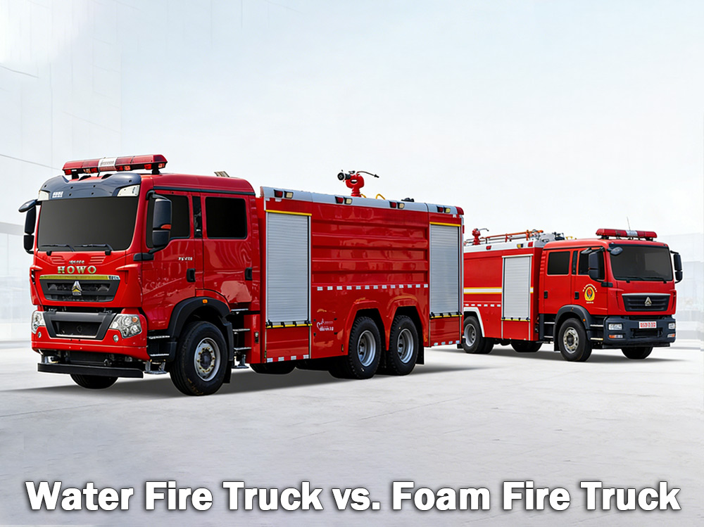
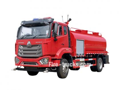
水消防车 普通消防车用于扑灭木材、纸张和布料等引起的火灾。泡沫消防车则用于扑灭汽油和油类等易燃液体引起的火灾。哪种消防车更合适,取决于具体的火灾隐患。 一个 水消防车 它配备一个大型水箱,依靠高压水泵通过软管或水炮输送水。它是世界各地市政消防部门和工业场所最常用的消防车类型。 一个 泡沫消防车 另一方面,水罐车是专门设计用于输送和喷洒消防泡沫的。当仅靠水无法有效扑灭火灾时——例如易燃液体、化学品或燃料火灾——泡沫是更好的选择。泡沫的作用原理是在火源上方形成一层泡沫层,隔绝氧气,防止复燃。 一、什么是水力消防车? 水罐消防车正如其名——一种配备大型水箱、强力水泵和水带或水炮的车辆,用于向火场供水。水箱通常可容纳500至3000加仑(约2000至12000升)的水。水泵从水箱或外部水源(例如消防栓、湖泊或池塘)抽水,然后通过高压水带将水输送到火场。 水基消防车最适用的地点: 水罐消防车非常适合 A类火灾 其中涉及普通可燃物: 木材 纸张和纸板 布料和织物 橡胶和塑料 草、灌木和林木材料 如果火灾涉及房屋、仓库或田地里的易燃物,通常用水就能扑灭。 水的局限性: 水有一个主要的弱点。当喷洒到汽油、油或化学品等燃烧的液体上时,由于水比这些燃料重,它会下沉。燃料则漂浮在水面上继续燃烧。在某些情况下,水甚至会使火势蔓延到更大的区域。这就是为什么单靠水无法有效扑灭易燃液体火灾的原因。 水力消防车消防泵规格: 水消防车 火警 规格: 二、什么是泡沫消防车? 泡沫消防车是一种专门用于运输和投放消防泡沫的车辆。它配备两个独立的储罐——一个用于装水,一个用于装泡沫浓缩液。泡沫比例混合系统将两者按特定比例混合,通常泡沫浓缩液与水的比例为1%、3%或6%。混合后的泡沫通过泡沫喷嘴,在喷嘴中注入空气,形成膨胀稳定的泡沫层。 泡沫的工作原理: 泡沫会在燃烧的液体或物质表面形成一层覆盖物。这层覆盖物: 切断火的氧气供应 冷却燃料表面 防止易燃气体逸出 阻止火势复燃 泡沫消防车最适用的场景: 泡沫消防车对于以下方面至关重要: B类火灾 其中包括易燃和可燃液体: 汽油和柴油 航空煤油和煤油 油和油脂 酒精和乙醇 工业化学品 对于某些仅靠水难以扑灭的 A 类火灾,例如堆放货物的仓库或轮胎存储设施的火灾,泡沫也同样有效。 常见应用: 应用 泡沫材料为何有效 机场 扑灭航空燃油火灾需要泡沫;用水无效。 炼油厂 现场有大量易燃液体 化工厂 漂浮在水面上并持续燃烧的化学物质 燃料储存库 到处都是汽油和柴油罐。 矿山和海�
细节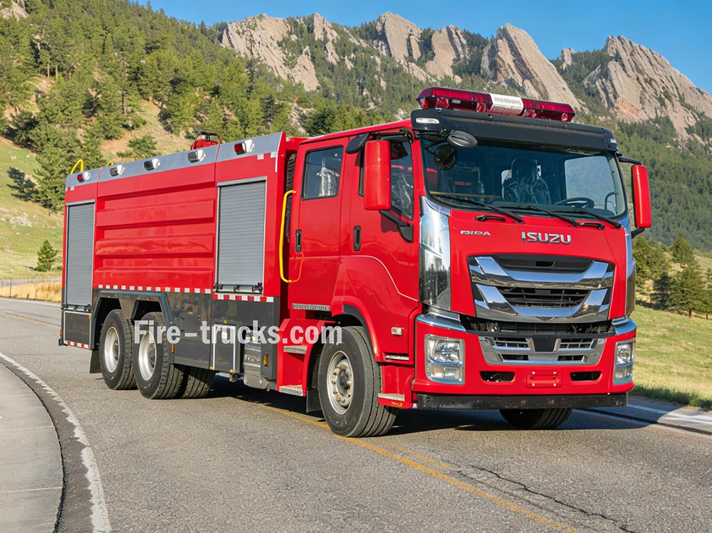
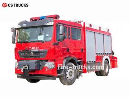
消防车 消防系统通过多个系统的协调运作来实现供水、压力产生和灭火。理解这些原理有助于消防人员在紧急情况下高效行动。 » Ⅰ. 消防车的工作原理: ▪ A. 水泵系统:灭火系统的核心: 消防车的核心部件是水泵。这个高功率装置从车载水箱或外部水源(例如消防栓、湖泊或池塘)抽取水,并通过高压软管输送出去。最常用的水泵是离心泵,它依靠旋转的叶轮来加压和输送水。 消防员通过泵控制面板上的一系列控制杆和压力表来控制水流。他们可以根据需要调节压力,并同时将水输送到多条水带。 泵类型 特征 最佳应用 单级离心泵 高流量,中等压力 市政消防 两级离心泵 音量和压力模式可切换 高层建筑,长长的软管铺设 多级泵 极高压力 工业设施,泡沫系统 ▪ 泵的关键参数: › 流量:每分钟 1,200 - 6,000 升(取决于型号) › 最大压力:1.0 - 2.5 MPa (10-25 bar) › 预热时间:≤30 秒 ▪ B. 水箱和储水系统: › 油箱容量:500 - 1,500 加仑(约 2,000 至 6,000 升),具体取决于车辆尺寸和类型 › 罐体材质:耐腐蚀不锈钢或涂层碳钢 › 内部挡板:多个隔间采用防涌流设计,可在应急响应期间控制水流。 › 注水时间:≤3分钟(通过消防栓或抽水) › 水位指示器:水箱侧面可视液位计;可选配驾驶室显示屏 水箱采用耐腐蚀材料制造,通常为不锈钢或涂层碳钢,内部设有挡板,用于控制紧急救援驾驶期间的水流冲击。 ▪ C. 软管和喷嘴系统 消防车配备各种不同功能的软管: › 攻击软管:直径 1.5 - 2.5 英寸——可将水直接输送到火源 › 供水软管:直径 4-5 英寸——从消防栓或其他水泵输送水 ›增压软管:卷盘式小直径软管——用于扑灭小型火灾,例如草地火灾或车辆火灾 水管末端的喷嘴可以让消防员控制水流,根据火灾类型调整压力、模式和方向。 ▪ D. 火警 › 水炮:可提供大流量水流,用于大规模灭火;可固定或远程操作 › 干粉灭火器:用于扑灭易燃液体、气体和电气火灾,可释放干粉化学灭火剂 › 组合式监测器:能够排出水和干粉;可根据需要切换介质 ▪ E. 发动机、动力传动系统和泵控制系统 发动机和动力总成系统 ● 发动机输出功率:300-600 马力——为车辆行驶和灭火系统提供动力 ● 发动机类型:大型柴油发动机——确保在城市街道或崎岖地形满负荷运行时性能可靠 ●动力输出装置(PTO):将发动机动力重新分配,用于驱动水泵、高空作业平台或其他液压系统。 控制面板 ● 转速表:显示发动机转速,以便调整油门 ● 压力表:监测不同排放点的低压、中压和高压。 ● 真空表:显示牵引作业期间的吸力压力 ● 液位指示�
细节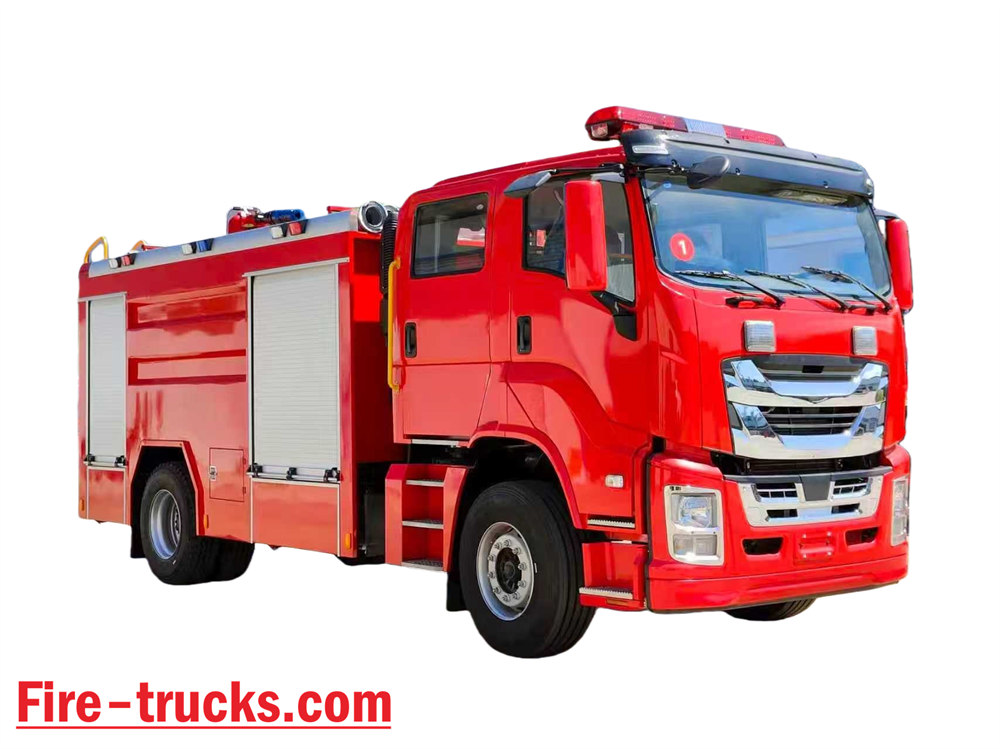
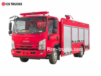
作为最专业的五十铃消防车生产厂家,五十铃NPR水泡沫消防车的核心设计是将泡沫灭火系统集成到水罐消防车中,形成可同时喷洒水和泡沫的复合型灭火设备。它既能独立灭火,又能向其他设备输送水或泡沫混合物,适用于干旱缺水地区的作业。 ★ 技术 规格 CS卡车公司生产的所有消防车,100%根据客户要求定制。 容量 发动机型号 水 泡沫 消防泵 火警 2500升 五十铃 4HK1 / 19 0马力 2500升 500升 CB10/40 消防泵 PL8/32 2026款五十铃消防车驾驶室底盘卡车 2026年消防车底盘原图 物品 五十铃消防车的设计细节 设计核心 将泡沫灭火系统集成到水罐消防车上,形成一辆既能喷洒水又能喷洒泡沫的双功能消防车。主要特点包括: • 独立灭火系统 • 向其他设备供应水或泡沫混合物 • 适用于干旱或缺水地区,可实现多功能用途 整体设计理念 该车辆专为满足车间及周边区域的消防需求而设计,增强了对油类、电气和固体物质火灾的扑救能力;车辆由底盘和专用车身设备组成,强调可靠性、多功能性和易操作性。 底盘选择 • 采用成熟的中型或重型 II 型底盘 • 建议采用全轮驱动,以提高在复杂地形中的机动性和牵引力 2026年全新设计的五十铃700P水力消防车 核心系统组件及设计要点 1. 水箱和泡沫液箱 • 材质:不锈钢,耐腐蚀 • 推荐容量:水箱 3000–5000 升,泡沫液箱 300–600 升 • 结构优化:内部挡板将水室和泡沫室分隔开来,可通过连接端口切换到单水箱模式,从而实现多用途使用。 2. 泡沫比例控制系统 • 采用平衡压力比例器(核心部件)以 3% 或 6% 的比例精确混合水和泡沫浓缩液。 • 输出稳定,不受流量或压力波动的影响,适合非专业操作人员使用 • 配备外部泡沫吸入口,方便现场补充泡沫 3. 排放系统 • 消防泵:高效节能多级离心泵,流量≥ 4 0 长/短 • 消防炮:遥控式水/泡沫两用炮,射程≥50米,角度可调 • 支持连接消防水带和泡沫喷嘴,操作灵活 2026年全新设计的五十铃NPR泡沫消防车 应用场景及优势 车间漏油火灾 非常适用;泡沫通过隔绝氧气迅速扑灭火焰。 初始电气设备起火 可以使用泡沫或混合干粉(确保电气绝缘安全) 固体物质燃烧 水炮可以直接有效地灭火 在缺水环境下作业 可作为供水保障车辆,实现长距离输水。 菲律宾五十铃4X2 FVR消防车 2000升水 + 500升泡沫容量 欧洲高品质人孔、梯子 五十铃 FTR 和 FVR 泡沫消防车技术图纸 五十铃水泡沫消防车的消防设备
细节
PF5-15 固定干粉监测器 该产品以干粉为介质,依靠固定底座实现稳定喷洒。适用于化工和仓储区域,能在火灾初期迅速覆盖燃烧表面,提高灭火效率。 这 PF5-15 固定式干粉监测仪 结构坚固,操作简便,可与自动控制系统连接,实现远程启动和精确喷洒。 » Ⅰ. PF5-15 固定式干粉监测仪 结构: PF5-15固定式干粉监测仪的特点: ● 功能齐全; ● 结构简洁新颖; ● 性能稳定,维护方便; ● 入口压力低; ● 配备有水平和垂直锁定功能的自动排水阀; ● 材质:精密铸造铝合金; ● 炮头:铝合金。 » 二、 泡沫炮 PL24 规格: 模型 流动 ( 公斤 /s ) 范围 ( 米 ) 额定工作压力 ( 百万 ) 投球旋转 ( ° ) 水平旋转 ( ° ) 长×宽×高 ( 毫米 ) 重量 ( 公斤 ) PF5-15/40 40 ≥42 0.80 -45 ~ +70 0 ~ 360 980x340x550 28.5 » Ⅲ. 产品应用: 配备PF5-15固定式干粉炮的消防车 PF5-15 固定式干粉监测仪测试 PF5-15型固定式干粉灭火器喷射距离远、覆盖范围广,能快速形成干粉灭火屏障。适用于化工厂、油库、储藏区等固定场所,可为大面积区域提供持续稳定的灭火能力。
细节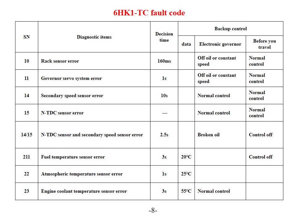
五十铃6HK1-TC消防车 也称作 五十铃救援消防车 发动机故障代码诊断及解决方案。 五十铃6HK1-TC发动机采用先进的TICS燃油喷射泵电子控制系统,其ECU(发动机控制单元)具备自诊断功能。当系统检测到故障时,“检查发动机”警告灯会亮起,并存储相应的故障代码。了解这些故障代码的含义和解决方法,可以有效提高发动机维护效率。 常见错误代码及解决方法 P系列故障代码 P0101(空气流量传感器电路低) 检查发动机冷却液温度传感器及其线路。确认传感器电源电压和接地连接正常。必要时更换ECU或传感器。 P0102(空气流量传感器电路高) 检查燃油质量和滤清器状况。清洗燃油系统。检查燃油压力调节器、燃油泵和喷油器电路。 P0103(质量空气流量传感器 A 电路高) 检查传感器信号电路是否存在短路。测试传感器的工作状态。如有必要,更换传感器或ECU。 数字故障代码 10(机架传感器错误) 检查机架传感器及其线路。确认信号传输正常。 11(调速伺服系统故障) 检查调速伺服系统的运行状态。测试相关电路连接。 14(辅助速度传感器故障) 检查辅助速度传感器的安装位置。测试传感器的信号输出。 15(N-TDC传感器误差) 检查 N-TDC 传感器连接 验证信号准确性 系统维护和预防措施 SN 诊断项目 决策时刻 备份控制 数据 电子调速器 旅行前 10 机架传感器故障 160毫秒 关闭油路或恒速 正常对照 11 调速伺服系统故障 1秒 关闭油路或恒速 正常对照 14 二级速度传感器故障 10秒 正常对照 正常对照 15 N-TDC传感器误差 — 正常对照 正常对照 14/15 N-TDC传感器和二次速度传感器误差 2.5秒 破油 关闭控制 211 燃油温度传感器故障 3秒 20℃ 关闭控制 22 大气温度传感器误差 1秒 25℃ 23 发动机冷却液温度传感器故障 3秒 55℃ 正常对照 连接器 航站楼号 信号 线径/线径 (喷油泵线束) 西南水利工程 8个末端 黑色的 1 调速器执行器驱动电压 - 1 RM 2 2 调压电路 GND-1 W/1.2 3 目标货架位置 - 1 U1 2 4 机架位置电压 G/1.2 5 调速器电路 5V-1 Y/1.2 6 备用 N 传感器(接地) BR/1.2 7 备用 N 传感器(信号) 0/1.2 8 下拉 B/1.2 SWP6- 终端 黑色的 克 调速器执行器驱动电压 - 2 R/1.2 10 目标货架位置 - 2 升/1.2 11 调压电路 GND-2 W/1.2 12 调压电路 SIG-GND BR/1.2 13 调速器电路 5V-2 Y/1.2 SWP 3- 终端 黑色的 14 跛着回家 W1.2 15 副线圈(未使用) BY/1.2 定期维护 按时更换发动机机油(根据里程和温度要求)。 更换三个滤清器(柴油滤清器、机油滤清器和空气滤清器) 使用适用于当地温度的柴油 操作规范 冷启动前(尤其是在冬季)要预热发动机。 夏季要维护好冷却系统,防止过热。 定期检查燃油系统,防止出
细节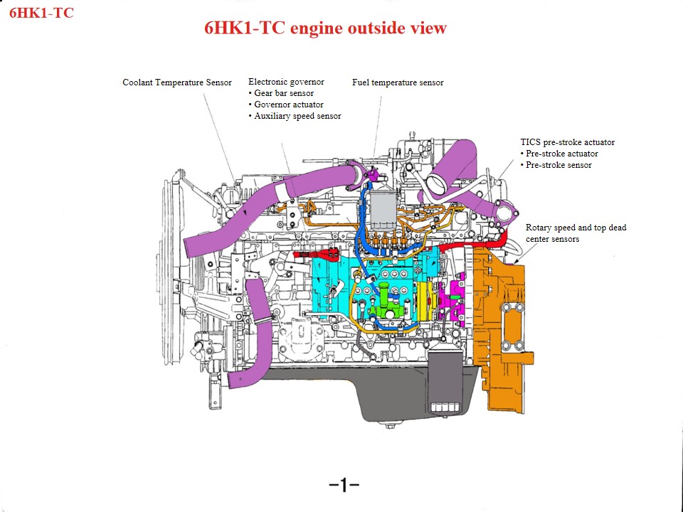
五十铃6HK1消防救援车 也称作 五十铃消防车 , 如果五十铃救援消防车发动机过热,应首先检查以下几个方面: 1. 冷却系统:风扇损坏、散热器堵塞、恒温器损坏或冷却液不足等问题都可能导致发动机过热。 2. 机油质量和数量:机油质量差或机油不足也会导致发动机过热。 3. 气缸爆裂、气缸套裂纹或气缸套破裂等机械故障也会导致这种现象。 作为一款重型柴油动力装置,五十铃6HK1发动机的维护保养必须严格遵守技术规范。要点如下: 1. 结构理解、拆卸和组装规范 曲轴连杆机构 气缸套采用松配合设计,需要专用工具防止其在拆卸和组装过程中脱落。标准间隙为0.122–0.156毫米。 活塞外径公差严格(114.894–114.909mm)。安装时,注意活塞环的开启方向以及“三间隙”(端隙、侧隙和背隙)的调整。 下曲轴箱为一体式结构,维护时必须吊装,以防止变形。 正时系统校准 变速箱组装过程中,对齐曲轴齿轮和惰轮齿轮的标记。凸轮轴B标记必须与气缸盖表面齐平。发动机应处于第一气缸压缩上止点。 安装燃油喷射泵时,将正时指针与连接器上的 S 点对齐,并将喷射提前器标记与泵体指针对齐。 • 线性直流电机在控制单元输出信号的作用下推动线圈上下运动。 • 安装在点火线圈组件上的连杆将点火线圈的上下运动传递给连接块,连接块安装在齿条的末端。在连接块的推动下,齿条左右移动以改变喷油量。当点火线圈组件向上移动时,连杆推动齿条增加喷油量;相反,当点火线圈组件向下移动时,齿条减少喷油量,而立柱的作用是将垂直运动转换为齿条的高度运动。 • 铜块安装在连接块的上部,构成齿条传感器。该齿条传感器检测齿条行程,并将该值反馈给控制单元,以便持续比较实际齿条行程和目标齿条行程,直至两者之差接近于零。此过程对于控制精度和响应速度至关重要。 2. 系统关键维护点 润滑和冷却系统 换油周期:矿物油:每 5,000 公里或 6 个月;合成油:8,000-10,000 公里。 冷却水进水口采用阶梯式设计,维护时需要按顺序拆卸。防冻液应每两年或行驶4万公里更换一次。 燃油和空气进气系统 柴油滤清器每行驶20000公里或警告灯亮起时更换。空气滤清器每行驶15000公里检查一次。 燃油系统需要定期清洗,以防止杂质影响喷射精度。 3. 维护程序和注意事项 工具和数据准备 使用扭矩扳手按照手册规格拧紧螺栓(例如喷油泵支架螺栓)。 维修前,请查阅“4HK1-6HK1 发动机维修手册”(第 332 页)以获取详细参数。 故障诊断逻辑 首先检查“三大过滤器”的状态,然后排查电子控制系统故障(例如ECU信号)。易损件应根据“摩擦三阶段�
细节
请继续阅读,保持关注,订阅,并欢迎您告诉我们您的想法。


 中文
中文 English
 français
 Deutsch
 русский
 italiano
 español
 português
 Nederlands
 العربية
 日本語
日本語 한국의
한국의 Türkçe
 Melayu
 ไทย
ไทย Tiếng Việt
 Indonesia
  қазақ
қазақ Filipino
 မြန်မာ
 српски

 支持IPv6网络